banner
Vibrating Screen Installation, Start up and Adjustments
Jul 02, 2020
Installation
The supporting steel structures on which the screen and drive motor are mounted must be sufficiently strong and braced to accept without deflection the dynamic loads caused by the
vibration of the screen.
Adequate clearances must be allowed between the screen and the fixed structure, chutes etc., to allow enough space because the movement of the screen is large in the so-called resonance areas when starting and stopping the screen.
Check that the height difference of separate springs pedestals (in the same end of the screen) are not more than ± 3 mm. Transparent water hose and water may be used to check the height difference. Pedestals surface must be horizontal.
Tighten all bolts in the recommended sequence if any and to the recommended torque.
  • Check the screen's installation angle.
  • Check that all of the spring axes are vertical.
  • Check rotation directions of the motor/s.
In case of screen driven by motor and cardan shaft, the vertical position of the motor must be fixed so that the centre line on the screen’s shaft is approx. 5 mm higher than the centre line of the motor shaft. During running with material, cardan shaft should be close to horizontal. In case of belt drive, tension the belts as per manufacturer’s recommendation.
Make sure that all guards are properly fastened and all the safety devices are installed and they are working properly.
Earth the motor connection at the mains.
Have qualified electrician install overload, short-circuit and ground-fault protection.
If unbalance motor is installed onto a vibrating screen, leave slack in electrical cable so that cable does not become taut during vibration cycle and cause stress on wire connection.
In case of a linear motion vibrating screen, interlock the two unbalance motors rotating in opposite directions and install separate overload protection. The screen’s control circuit must be arranged so that if one unbalance motor becomes de-energized, the other unbalance motor will automatically and immediately become de-energized. Failure to properly interlock screen’s unbalance motors could result in damage to the screen if one unbalance motor fails (if only one unbalance motor of a pair is powered, the bearings in the unpowered unbalance motor will get damaged within a very short time).
If the unit is going to be stored before start-up, once a month, the shaft should be rotated several times to re-lubricate the upper bearing portion.


Start up
After start (first 1-2 minutes) make sure that screen is starting and running properly.
Check the feed of the material. It must spread to whole width of the screen.
Check screening result.

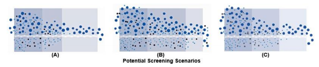
Above figure shows three potential screening scenarios. Screening finishes early on the
deck at (A), which results in a loss of production; screening not completed (B), which results
in carryover and contaminated material; and optimal screening (C), which provides for higher
production with less contamination.
Check stroke length and stroke angles in each corner. Stroke length must be within one mm to each other in the same end of the screen!
Check for oil/grease leaks in the mechanism.
After 4 to 6 hours, check that bearing temperature is even in each bearing. Normal running temperature can be about 70°C when ambient temp is 20°C.
After running the screen for about 50 hours, check the following:

  • Fastening / tightness of mechanism bolts.
  • Fastening / tightness of counterweight.
  • Fastening of screening medias.
  • Alignment / tightness of V-belts.
Mechanism has tendency to leak a little bit after few operation hours or days. This leak is mainly extra grease coming out of sealing. Leaking should stop in few hours or days.
The first oil change for the mechanism must be done as per manufacturer’s recommendation
(in case of gears, after about 100 hours of operation).


Screen Adjustments
If the screening performance is not satisfactory, check first that the screen meshes are correct for the application and that the feed and discharge arrangements are satisfactory. Feed to the screen must be arranged so that the material is fed uniformly across the entire width of the screen.
As feed material is a mixture of varying sizes, oversize material will restrict the passage of undersize material, which results in a build-up, or bed depth, of material on the screen surface. Bed depth diminishes as the undersize material passes through the screen openings. For efficient screening, the material bed should not reach a depth that prevents undersize from stratifying before it is discharged. Hence for maximum screening efficiency depth of bed should be proper. As stated earlier, depth of bed (in dry screening) should not
exceed four times the opening size at the discharge end of the screen. Depth of bed can be
changed by adjustments in speed, stroke length, rotation (or throw) direction and angle of
inclination. However, always make only the minimum adjustments necessary to achieve the
desired result.
If adjustments are necessary, they should be made in the order given below.


  • Stroke frequency adjustment

  • Stroke length adjustment

  • Adjusting the inclination of the screen body

Try the action of each measure separately and singly. Try one action at a time and observe
the result before taking on the next one.
Adjustment of the stroke length is done by adding or removing counterweights. At both ends of the same shaft there has to be exactly the same number of counterweights. Higher stroke delivers a higher carrying capacity and travel rate, while reducing plugging, blinding and enhancing stratification. Always check the screen speed/stroke length combination so that the maximum allowed acceleration (G-force) of the screen is not exceeded.
Stroke frequency adjustment can be done by changing V-belt pulleys or inverter parameters.
Higher frequency/speed may decrease depth of bed. Rotation speed affects the G-forces.
More speed, more G-forces with same counter weights.
Always ask manufacturer before changing rotation speed. Wrong speed can run the screen near to its natural frequency leading to screen body failure.
Also remember that increased G-forces shortens the bearing life time!
Adjusting the inclination of the screen body is done by lifting or lowering other end of the screen or feeder. Increasing the angle of inclination causes material to travel faster, which can be advantageous in certain dry screening applications. Although, there may be a point where too much incline will hinder efficiency as fines may roll over the media rather than passing through.
Do consult the manufacturer for advice on the selection of the optimum speed, stroke length, angle and frequency, if mesh sizes are changed or different material is fed to the screen.


Standard or Custom Bulk material
What is better for your project?

call us :

+86 18601767509
Leave a message
If you are interested in our products and want to know more details,please leave a message here,we will reply you as soon as we can.
copyright © 2024 Anhui VRV industrial technology co.,ltd..all rights reserved. powered by dyyseo.com /
ipv6 network supportedipv6 network supported
Leave a message
VRV
If you are interested in our products and want to know more details,please leave a message here,we will reply you as soon as we can.

home

products

about

contact